Well, almost… 32GFC is fixed and at the standard has been ratified and the physical specs are moulded in concrete. In addition to this there are functions that enable to combine 4 of these into a single 128Gb link. Yes 128Gb/s. That’s fast….Ohhh wait… thats only ONE WAY which means a single link can push 256Gb/s in total. That allows you to push 25600MB per second through a link. In order to achieve these transmission speeds there has been a somewhat restructuring on the individual requirements w.r.t. quality of the actual link.
Tag Archives: fibre channel
CRC errors
In Fibre-Channel, and many other network protocols, the use of CRC (Cyclic Redudancy Check) is adopted to detect corruption of frames. Be aware of the word “frames”!! As I explained in previous posts there are two layer of link integrity, an 8b/10b encoding/decoding algorithm (on 10G and 16G FC it has been changed to 64/66) which ensures dc balance plus error detection on the FC1 layer plus CRC which provides an additional check on the FC2 layer. Primitive signals or sequences are not frames and thus are not guarded with a CRC check.
Crc has the benefit that it can calculate on a serial bitstream as opposed to some other methods which require a certain fixed size of data in order to provide an integrity check. (A PKI like infrastructure is something along these lines such as GPG which can cryptographically sign an email message based on the entire content before it is sent). Secondly the calculation and reverse checking is very simple which means it can be build in hardware (ASICs or FPGA’s) without the need for software spending CPU cycles on both ends of the link which would have a serious impact on performance. There is absolutely no integrity check or security mechanism build into crc so any content can easily be modified, the crc recomputed and forwarded without the receiving side knowing it. In my test environments I use such methods to change an FC frame in-flight in order to see the behaviour of the modified content on the HBA or array. This allows me to inject data to test on protocol errors and the subsequent actions. (If I wasn’t able to recompute the crc, the destination port would detect the incorrect crc and just discard the frame.)
Now, going back to Fibre Channel. The CRC is calculated from the Start Of Frame (SOF) until the last word of the payload and is then appended to the frame. The FC2 layer will then add an End Of Frame (EOF) with a status qualifier. (I get back to this later).

Below a screenshot of a FC trace where the host issued a write(10) command to lun 32. The CRC is determined to be correct and the frame is ended with a EOFt (terminate, this doesn’t mean the IO is terminated but this sequence of the FC exchange is completed. I won’t go into this any further)
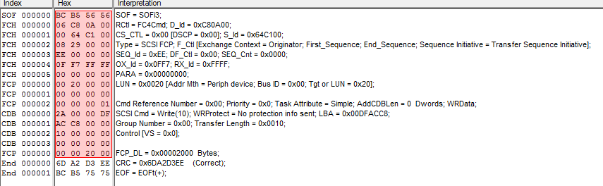
If for any reason one or more bits in the bitstream between the SOF and last bit of the payload is changed the receiving side will do a reverse crc check which obviously will fail.
Now, I mentioned that the calculation is done inline of the bitstream. These days all fibre-channel implementations from all vendors use cut-through switching which more or less means that as soon as the first word of the FC frame is received (the one that contains the DID Destination ID or FCID) it is immediately forwarded to the out-port of that switch having the route set up according to FSPF. The second word of the frame may not even have arrived in full yet. This ensures optimal performance with next to no latency from a switching algorithm perspective. If you then do some maths and calculate the length of a FC frame it means that the first word of the frame may have already arrived at its final destination before the last word of the frame has even left the source.
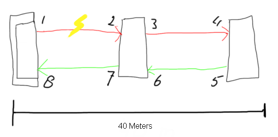 In the above picture you see a representation of three switches (pardon my drawing skills). Switch number one on the left has received a frame from an HBA and is sending this out on port 1. The frame is 1KB in size and the link speed is 8Gb/s. This means that the length of the frame is almost 250 meters long. If one or more bits flip at the 512th byte on the link between 1 and 2 the beginning of the frame is already at it’s destination so nowhere in the entire FC path any form of correction can be done. (there is an exception called FEC but I’ll discuss this in a later post). What will happen is that the port at (2) will detect the crc error and it will replace the EOFn or EOFt with a EOFni or EOFti (the i means invalid.) All switches will forward the frame to its destination (unless the DID in the frame-header is the part which is corrupt). As soon as the EOFxi arrives at the destination it can immediately discard the entire frame, clear the buffer and start the recovery procedures. If the intermediate switch detects the crc error and it would have discarded the frame over there both the initiator and target would have no clue what’s going on and would rely on the default FC and SCSI timeout values before is would be able to act on these.
From a troubleshooting perspective if you now look on the error counters on the switch ports (on a Brocade platform) you will see that port (2) will have logged the crc error in two columns of the porterrshow output: the crc_err and crc_g_eof (CRC error with a good EOF). Since the intermediate switch still forwards the frame port (4) will also detect the same crc error however since port (2) changes the EOFx into an EOFxi (invalid) port only the crc_err column on this port is incremented and not the crc_g_eof column. This mechanism allows you to follow upstream paths and determine where these errors originate from.
Hope this brings some insight and gives you better info of how to interpret these kind of errors.
Regards,
Erwin
Unable to provision new Luns (and how to solve it)
A fair number of people have reported that when they want to provision storage to a host this doesn’t seem to work. Only after bouncing a FC port or rebooting the host these LUNs become visible. Others reported that it only works when they provision LUNs and zones in a particular order. So how is this possible? Continue reading
Why Fibre-Channel has to improve
Many of you have used and managed fibre-channel based storage networks over the years. It comes to no surprise that a network protocol primarily developed to handle extremely time-sensitive operations is build with extreme demand regarding hardware and software quality and clear guidelines on how these communications should proceed. It is due to this that fibre-channel has become the dominant protocol in datacenters for storage. Continue reading
Closing the Fibre-Channel resiliency gap – 2
So this morning I uploaded my proposal to T11 (13-348v0) in order to get the ball rolling to get it adopted in the FC-LS-3 standard. (That would be awesome). Obviously the task to get things done in a very stable protocol which is known for some serious backward compatibility is not an easy undertaking. I’ve tried (and I think I succeeded) in leaving all existing behaviour intact. This way any transition towards an environment that supports this new architecture is seamless.
The document should be download-able for everyone so any feedback is highly appreciated.
Cheers,
Erwin
Closing the Fibre-Channel resiliency gap
Fibre-Channel is still the predominant transport protocol for storage related data transmission. And rightfully so. Over the past +-two decades it has proven to be very efficient and extremely reliable in moving channel based data transmissions between initiators and targets. The reliability is due to the fact the underlying infrastructure is almost bulletproof. Fibre-Channel requires very high quality hardware as per FC-PI standard and a BER (Bit Error Rate) of less than 10^12 is not tolerated. What Fibre-Channel lacks though is an method of detection and notification to and from hosts if a path to a device is below the required tolerance levels which can cause frames to be dropped without a host to be able to adjust its behaviour on that path. Fibre-Channel relies on upper level protocols (like SCSI) to re-submit the command and that’s about it. When FC was introduced to the market back in the late 90’s, many vendors already had multipath software which could correlate multiple paths to the same LUN into one and in case one path failed it could switch over to the other. Numerous iterations further down the road nothing really exciting has been developed in that area. As per the nature of the chosen class-of-service (3) for the majority of todays FC implementations there is no error recovery done in an FC environment. As per my previous post you’ve seen that MPIO software is also NOT designed to act on and recover failed IO’s. Only in certain circumstances it will fail a path in a way that all new IO’s will be directed to one or more of the remaining paths to that LUN. The crux of the problem is that if any part of the infrastructure is less than what is required from a quality perspective and there is nothing on the host level that actively reacts on these kind of errors you will end up with a very poor performing storage infrastructure. Not only on the host that is active on that path but a fair chance exists other hosts will have the same or similar problems. (see the series of Rotten Apples in previous posts.)
So what is my proposal. Hosts should become more aware of the end-to-end error ratio of paths from their initiators to the targets and back. This results in a view where hosts (or applications) can make a judgement call of which path it can send an IO so the chances of an error are most slim. So how does this need to work. I is all about creating an inventory of least-error-paths. For this to be accomplished we need a way of getting this info to the respective hosts. Basically there are two ways of doing this. 1. Either create a central database which receives updates from each individual switch in the fabric and the host needs to query that database and correlate that with the FSPF (Fabric Shortest Path First) info in order to be able to sort things out or, and this would be my preferred way, we introduce a new ELS frame which can hold all counters currently specified in the LESB (Link Error Status Block) plus some more for future use or vendor specific info. I call this the Error Reporting with Integrated Notification frame. This frame is sent by the initiator to the target over all paths it has at its disposal. Each ingress port (RX port on each switch) which this frame traverses and increment the counters with its own values. When the target receives the frames it flips the SID and DID and send it back to the host. Given the fact this frame is still part of the same FC exchange it will also traverse the same path back so an accurate total error count of that path can be created.
Both options would enable each host of analyzing the overall error count on each path from HBA to target for each lun it has. The problem with option 1 is that the size of the database will increase exponentially proportional with the number of ports and paths and this might become such a huge size that it cannot live inside the fabric anymore and thus needs to be updated in an external management tool. This then has the disadvantage that host are depending on OOB network restrictions and security implications in addition to interop problematic issues. It also has the problem that path errors can be bursty depending on load and/or fabric behaviour. This management application will need to poll these switches for each individual port which will cause an additional load on the processors on each switch even while not necessary. Furthermore it is highly unreliable when the fabric is seeing a fair amount of changes which by default causes re-routing to occur and thus renders a calculation done by the host one minute ago, totally useless.
Option two has the advantage that there is one uniform methodology which is distributed on each initiator, target and path. It therefore has no impact on any switch and/or external management application and is also not relying on network (TCP/IP) related security restrictions, Ethernet boundaries caused by VLANS etc or any other external factors that could influence the operation.
The challenge is however that today there is no ASIC that supports this logic and even if I could get the proposal accepted by T11 it’ll take a while before this is enabled in hardware. In the meantime the ELS frame could be sent to the processor of the switch which in turn does the error count modification in the frame payload, CRC recalculation and other things required. Once more the bottleneck of this method will become the capability of the CPU of that particular switch especially when you have many high port-count blades installed . Until the ASICs are able to do this on the fly in hardware there will be less granularity from a timing perspective since each ELS frame will need to be sent to the CPU. To prevent the CPU from being flogged by all these update and pull requests in the transitional period there is an option to either extend the PLOGI to check if all ports in the path are able to support this frame in hardware or use this new ELS with a special “inventory bit” to determine the capabilities. If any port in the part does not not support the ELS frame it will flick it to 0. This allows the timing interval of each ELS frame to be inline with the capabilities of the end-to-end path. You can imagine that if all ports are able to do this in hardware you can achieve a much finer granularity on timing and hosts can respond much quicker on errors. If any port does not support the new ELS frame the timing can be adjusted to fall in between the E_D_TOV and R_A_TOV values (in general 2 and 10 seconds). The CPU’s on the switches are fairly capable to handle this. This is still much better than any external method of collecting fibre-channel port errors and having an out-of-band query and policy method. Another benefit is that there is a standard method of collecting and distributing the end-to-end path errors so even in multi-vendor environments it is not tied to a single management platform.
So lets look at an example.
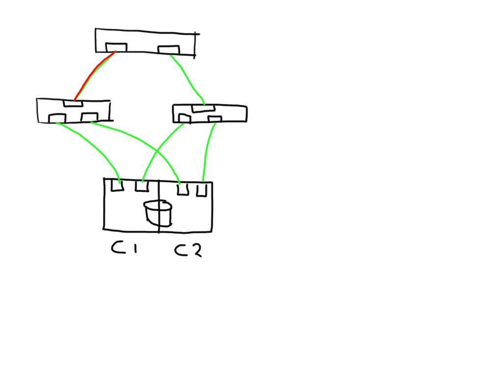
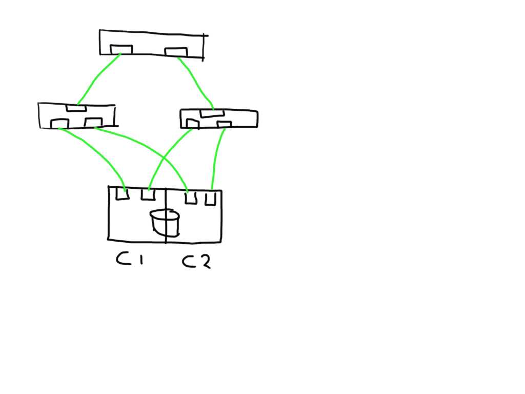 This shows a very simplistic SAN infrastructure where one host has 4 paths over two initiators to 2 storage ports each. All ports seem to be in tip-top shape.
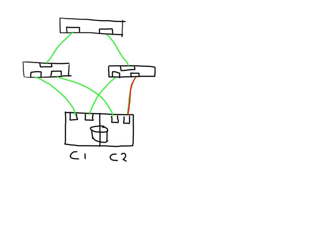 If one link (in this case between the switch and the storage controller) is observing errors (in any direction) the new ELS frame would increment that particular LESB counter value and the result would enable the host to detect the increase in any of the counters on that particular path. Depending on the policies of the operating system or application it could direct the MPIO software to mark that path failed and to remove it from the IO path list.
Similarly if a link shows errors between an initiator and switch it will mark 2 paths as bad and has the option to mark these both as failed.
 If you have a meshed fabric the number of paths exponentially grow with each switch and ISL you add. The below show the same structure but because an ISL has been added between the switches the number of potential paths between the host and LUN now grows to 8
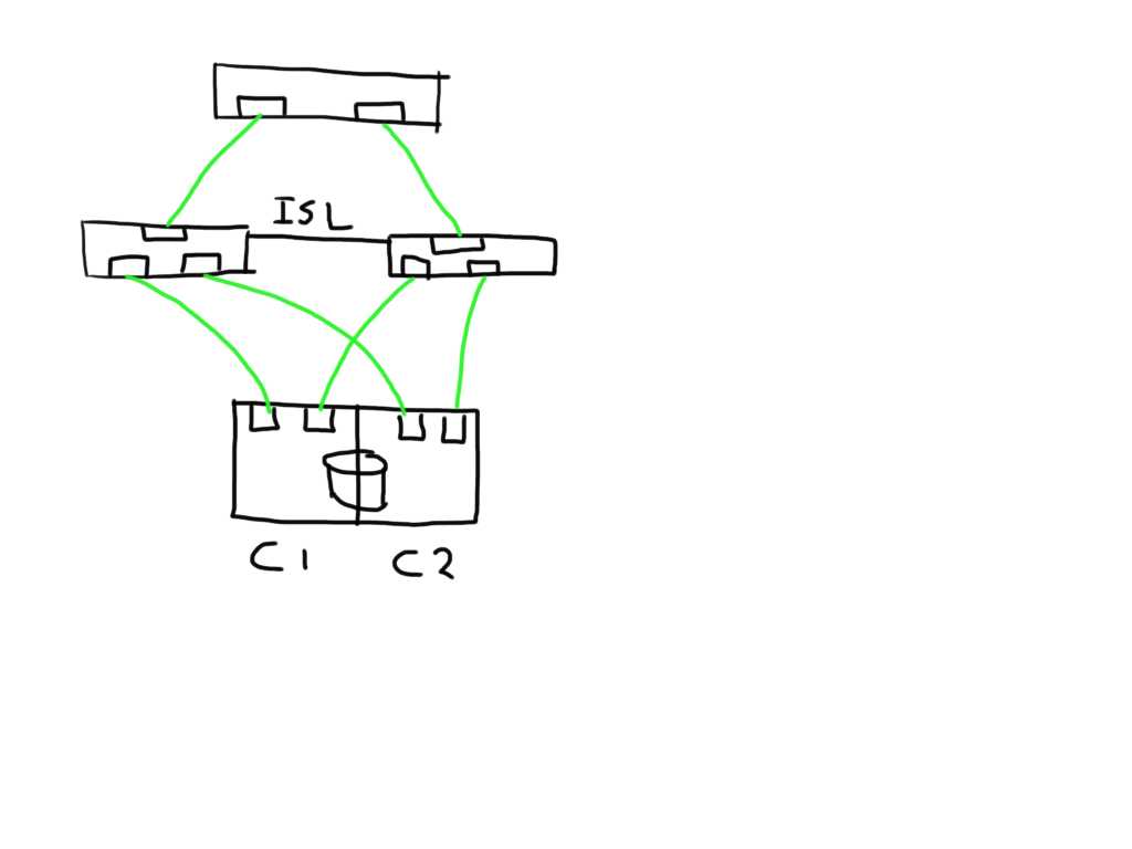 This means that if one of the links is bad the number of potential bad paths also duplicates.
 In this case the paths from both initiators on this bad link are marked faulty and can be removed from the target list by the MPIOsoftware.
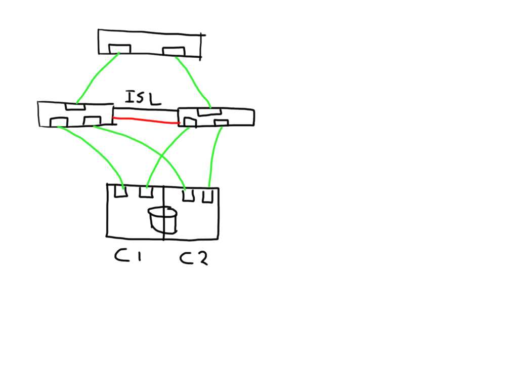 The fun really starts with the unexpected. Lets say you add an additional ISL and for some reason this one is bad. The additional ISL does not add new paths to the path-list on the host since this is transparent and is hidden by the fabric. Frames will just traverse one or the other irrespective of which patch is chosen by the host software. Obviously, since the ELS is just a normal frame, the error counters in the ELS might be skewed based on which of the two ISL’s it has been sent. Depending on the architecture of the switch you’ll have two options, either the ASIC accumulates all counters for both ports into one and add these onto the already existing counters, or you can use a divisional factor where the ASIC sums up all counters of the ISL’s and divides them by the number of ISL’s. The same can be done for trunks(brocade) / portchannels(Cisco). Given the fact that currently most the counters are used in 32bit transmission words the first option is likely to cause the counters to wrap very quickly. The second advantage of a divisional factor is that there will be a consistent averaging across all paths in case you have a larger meshed fabric and thus it will provide a more accurate feedback to the host.
I’m working out the details w.r.t. the internals of the ELS frame itself and which bits to use in which position.
This all should make Fibre-Channel in combination with intelligent host-based software an even more robust protocol for storage based data-transmissions.
Let me know what you think. Any comments, suggestions and remarks are highly appreciated.
Cheers
Erwin