After a very busy couple of weeks I’ve spent some time to dissect the release notes of Brocade FOS 7.1 and I must say there are some really nice features in there but also some that I REALLY think should be removed right away.
It may come to no surprise that I always look very critical to whatever come to the table from Brocade, Cisco and others w.r.t. storage networking. Especially the troubleshooting side and therefore the RAS capabilities of the hardware and software have a special place in my heart so if somebody screws up I’ll let them know via this platform. 🙂
So first of all some generics. FOS 7 is supported on the 8 and 16G platforms which cover the Goldeneye2,Condor2 and Condor 3 ASICs plus the AP blades for encryption, SAN extension and FCoE. (cough, cough)….Be aware that it doesn’t support the blades based on the older architecture such as the FR4-18i and FC10-6 (which I think was never bought by anyone.) Most importantly this is the first version to support the new 6520 switch so if you ever think of buying one it will come shipped with this version installed.
Software
As for the software features Brocade really cranked up the RAS features. I especially do like the broadening of the scope for D-ports (diagnostics port) to include ICL ports but also between Brocade HBA’s and switch ports. One thing they should be paying attention to though is that they should sell a lot more of these. :-). Also the characteristics of the test patterns such as test duration, frame-sizes and number of frames can now be specified. Also FEC (Forward Error Correction) has been extended to access gateways and long distance ports which should increase stability w.r.t. frame flow. (It still doesn’t improve on signal levels but that is a hardware problem which cannot be fixed by software).
There are some security enhancements for authentication such as extended LDAP and TACACS+ support.
The 7800 can now be used with VF albeit not having XISL functionality.
Finally the E_D_TOV FC timer value is propagated onto the FCIP complex. What this basically means that previously even though an FC frame had long timed-out according to FC specs (in general 2 seconds) it could still exist on the IP network in a FCIP packet. The remote FC side would discard that frame anyway thus wasting valuable resources. With FOS 7.1 the FCIP complex on the sending side will discard the frame after E_D_TOV has expired.
One of the most underutilised features (besides Fabric Watch) is FDMI (Fabric Device Management Interface). This is a separate FC service (part of the new FC-GS-6 standard) which can hold a huge treasure box of info w.r.t. connected devices. As an example:
FDMI entru
————————————————-
switch:admin> fdmishow
Local HBA database contains:
10:00:8c:7c:ff:01:eb:00
Ports: 1
10:00:8c:7c:ff:01:eb:00
Port attributes:
FC4 Types: 0x0000010000000000000000000000000000000000000000000000000000000000
Supported Speed: 0x0000003a
Port Speed: 0x00000020
Frame Size: 0x00000840
Device Name: bfa
Host Name: X3650050014
Node Name: 20:00:8c:7c:ff:01:eb:00
Port Name: 10:00:8c:7c:ff:01:eb:00
Port Type: 0x0
Port Symb Name: port2
Class of Service: 0x08000000
Fabric Name: 10:00:00:05:1e:e5:e8:00
FC4 Active Type: 0x0000010000000000000000000000000000000000000000000000000000000000
Port State: 0x00000005
Discovered Ports: 0x00000002
Port Identifier: 0x00030200
HBA attributes:
Node Name: 20:00:8c:7c:ff:01:eb:00
Manufacturer: Brocade
Serial Number: BUK0406G041
Model: Brocade-1860-2p
Model Description: Brocade-1860-2p
Hardware Version: Rev-A
Driver Version: 3.2.0.0705
Option ROM Version: 3.2.0.0_alpha_bld02_20120831_0705
Firmware Version: 3.2.0.0_alpha_bld02_20120831_0705
OS Name and Version: Windows Server 2008 R2 Standard | N/A
Max CT Payload Length: 0x00000840
Symbolic Name: Brocade-1860-2p | 3.2.0.0705 | X3650050014 |
Number of Ports: 2
Fabric Name: 10:00:00:05:1e:e5:e8:00
Bios Version: 3.2.0.0_alpha_bld02_20120831_0705
Bios State: TRUE
Vendor Identifier: BROCADE
Vendor Info: 0x31000000
———————————————-
and as you can see this shows a lot more than the fairly basic nameserver entries:
——————————————-
N 8f9200; 3;21:00:00:1b:32:1f:c8:3d;20:00:00:1b:32:1f:c8:3d; na
FC4s: FCP
NodeSymb: [41] “QLA2462 FW:v4.04.09 DVR:v8.02.01-k1-vmw38”
Fabric Port Name: 20:92:00:05:1e:52:af:00
Permanent Port Name: 21:00:00:1b:32:1f:c8:3d
Port Index: 146
Share Area: No
Device Shared in Other AD: No
Redirect: No
Partial: No
LSAN: No
——————————————
Obviously the end-device needs to support this and it has to be enabled. (PLEASE DO !!!!!!!!) It’s invaluable for troubleshooters like me….
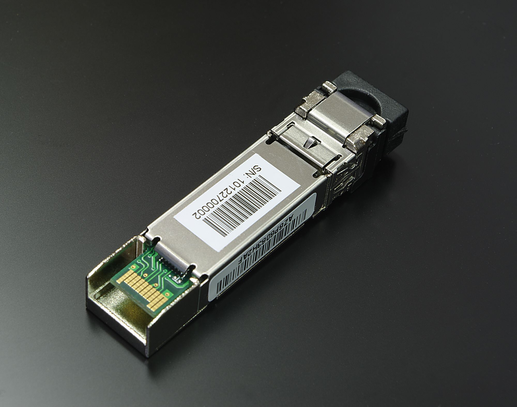
One thing that has bitten me a few times was the SFP problem. There has long been a problem that when a port was disabled and a new SFP was plugged in the switch didn’t detect that until the port was enabled and it had polled for up-to-date information. In the mean time you could get old/cached info of the old SFP including temperatures, db values, current, voltage etc.. This seems to be fixed now so thats one less thing to take into account.
Some CLI improvements have been made on various commands with some new parameters which lets you filter and select for certain errors etc.
The biggest idiocracy that has been made with this version is to allow the administrator change the severity level of event-codes. This means that if you have a filter in BNA (or whatever management software you have) to exclude INFO level messages but certain ERROR or CRITICAL messages start to annoy you you could change the severity to INFO and thus they don’t show up anymore. This doesn’t mean th problem is less critical so instead of just fixing the issue we now just pretend it’s not there. From a troubleshooting perspective this is disastrous since we look at a fair chuck of sup-saves each day and if we can’t rely on consistency in a log file it’s useless to have a look in the first place. Another one of those is the difference in deskew values on trunks when FEC is enabled. Due to a coding problem these values can differ up to 40 therefore normally depicting a massive difference in cable length. Only by executing a d-port analysis you can determine if that is really the case or not. My take is that they should fix the coding problem ASAP.
A similar thing that has pissed me off was the change in sfpshow output. Since the invention of the wheel this has been the worst output in the brocade logs so many people have scripted their ass off to make it more readable.
Normally it looks like this:
=============
Slot 1/Port 0:
=============
Identifier: 3 SFP
Connector: 7 LC
Transceiver: 540c404000000000 2,4,8_Gbps M5,M6 sw Short_dist
Encoding: 1 8B10B
Baud Rate: 85 (units 100 megabaud)
Length 9u: 0 (units km)
Length 9u: 0 (units 100 meters)
Length 50u: 5 (units 10 meters)
Length 62.5u:2 (units 10 meters)
Length Cu: 0 (units 1 meter)
Vendor Name: BROCADE
Vendor OUI: 00:05:1e
Vendor PN: 57-1000012-01
Vendor Rev: A
Wavelength: 850 (units nm)
Options: 003a Loss_of_Sig,Tx_Fault,Tx_Disable
BR Max: 0
BR Min: 0
Serial No: UAF11051000039A
Date Code: 101212
DD Type: 0x68
Enh Options: 0xfa
Status/Ctrl: 0xb0
Alarm flags[0,1] = 0x0, 0x0
Warn Flags[0,1] = 0x0, 0x0
Alarm Warn
low high low high
Temperature: 31 Centigrade -10 90 -5 85
Current: 6.616 mAmps 1.000 17.000 2.000 14.000
Voltage: 3273.4 mVolts 2900.0 3700.0 3000.0 3600.0
RX Power: -2.8 dBm (530.6uW) 10.0 uW 1258.9 uW 15.8 uW 1000.0 uW
TX Power: -3.3 dBm (465.9 uW)125.9 uW 631.0 uW 158.5 uW 562.3 uW
and that is for every port which basically makes you nuts.
So with some bash,awk,sed magic I scripted the output to look like this:
Port  Speed   Long  Short  Vendor     Serial            Wave   Temp   Current  Voltage   RX-Pwr   TX-Pwr
              wave  wave              number            Length
1/0   8G      NA    50 m   BROCADE    UAF11051000039A   850    31     6.616    3273.4   -2.8      -3.3
1/1   8G      NA    50 m   BROCADE    UAF110510000387   850    32     7.760    3268.8   -3.6      -3.3
1/2   8G      NA    50 m   BROCADE    UAF1105100003A3   850    30     7.450    3270.7   -3.3      -3.3      etc....
From a troubleshooting perspective this is so much easier since you can spot issues right away.
Now with FOS 7.1.x the FOS engineers screwed up the SFPshow output which inherently screwed up my script which necessitates a load more work/code/lines to get this back into shape. The same thing goes for the output on the number of credits on virtual channels.
Pre-FOS 7.1 it looks like this:
C:—— blade port 64: E_port ——————————————
C:0xca682400: bbc_trc 0004 0000 002a 0000 0000 0000 0001 0001
With FOS 7.1 it looks like this:
bbc registers
=============
0xd0982800: bbc_trc 20 0 0 0 0 0 0 0
(Yes, hair pulling stuff, aaarrrcchhhh)
Some more good things. The fabriclog now contains the direction of link resets. Previously we could only see an LR had occurred but we didn’t see who initiated it. Now we can and have the option to figure out in which direction credit issues might have been happening. (phew..)
The CLI history is now also saved after reboots and firmware-upgrades. Its been always a PITA to figure out who had done what at a certain point-in-time. This should help to try and find out.
One other very useful thing that has been added and it a major plus in this release is the addition of the remote WWNN of a switch in the switchshow and islshow output even when the ISL has segmented for whatever reason. This is massively helpful because normally you didn’t have a clue what was connected so you also needed to go through quite some hassle and check cabling or start digging through the portlogdump with some debug flags enabled. Always a troublesome exercise.
The bonus points from for this release is the addition of the fabretrystats command. This gives us troubleshooters a great overview of statistics of fabric events and commands.
SW_ILS
————————————————————————————————————–
E/D_Port ELP EFP HA_EFP DIA RDI BF FWD EMT ETP RAID GAID ELP_TMR GRE ECP ESC EFMD ESA DIAG_CMD
————————————————————————————————————–
0 0 0 0 0 0 0 0 0 0 0 0 0 0 0 0 0 0 0
69 0 0 0 0 0 0 0 0 0 0 0 0 0 0 0 0 0 0
71 0 0 0 0 0 0 0 0 0 0 0 0 0 0 0 0 0 0
79 0 0 0 0 0 0 0 0 0 0 0 0 0 0 0 0 0 0
131 0 0 0 0 0 0 0 0 0 0 0 0 0 0 0 0 0 0
140 0 0 0 0 0 0 0 0 0 0 0 0 0 0 0 0 0 0
141 0 0 0 0 0 0 0 0 0 0 0 0 0 0 0 0 0 0
148 0 0 0 0 0 0 0 0 0 0 0 0 0 0 0 0 0 0
149 0 0 0 0 0 0 0 0 0 0 0 0 0 0 0 0 0 0
168 0 0 0 0 0 0 0 0 0 0 0 0 0 0 0 0 0 0
169 0 0 0 0 0 0 0 0 0 0 0 0 0 0 0 0 0 0
174 0 0 0 0 0 0 0 0 0 0 0 0 0 0 0 0 0 0
175 0 0 0 0 0 0 0 0 0 0 0 0 0 0 0 0 0 0
This release also fixes a gazillion defects so its highly advisable to get to this level better sooner than later. Check with your vendor for the latest supported release.
So all in all good stuff but some things should be reverted, NOW!!!. and PLEASE BROCADE: don’t screw up more output in such a way it breaks existing analysis scripts etc…
Cheers
Erwin