A fair number of people have reported that when they want to provision storage to a host this doesn’t seem to work. Only after bouncing a FC port or rebooting the host these LUNs become visible. Others reported that it only works when they provision LUNs and zones in a particular order. So how is this possible? Continue reading
Category Archives: Fibre Channel
Why Fibre-Channel has to improve
Many of you have used and managed fibre-channel based storage networks over the years. It comes to no surprise that a network protocol primarily developed to handle extremely time-sensitive operations is build with extreme demand regarding hardware and software quality and clear guidelines on how these communications should proceed. It is due to this that fibre-channel has become the dominant protocol in datacenters for storage. Continue reading
Closing the Fibre-Channel resiliency gap – 2
So this morning I uploaded my proposal to T11 (13-348v0) in order to get the ball rolling to get it adopted in the FC-LS-3 standard. (That would be awesome). Obviously the task to get things done in a very stable protocol which is known for some serious backward compatibility is not an easy undertaking. I’ve tried (and I think I succeeded) in leaving all existing behaviour intact. This way any transition towards an environment that supports this new architecture is seamless.
The document should be download-able for everyone so any feedback is highly appreciated.
Cheers,
Erwin
Closing the Fibre-Channel resiliency gap
Fibre-Channel is still the predominant transport protocol for storage related data transmission. And rightfully so. Over the past +-two decades it has proven to be very efficient and extremely reliable in moving channel based data transmissions between initiators and targets. The reliability is due to the fact the underlying infrastructure is almost bulletproof. Fibre-Channel requires very high quality hardware as per FC-PI standard and a BER (Bit Error Rate) of less than 10^12 is not tolerated. What Fibre-Channel lacks though is an method of detection and notification to and from hosts if a path to a device is below the required tolerance levels which can cause frames to be dropped without a host to be able to adjust its behaviour on that path. Fibre-Channel relies on upper level protocols (like SCSI) to re-submit the command and that’s about it. When FC was introduced to the market back in the late 90’s, many vendors already had multipath software which could correlate multiple paths to the same LUN into one and in case one path failed it could switch over to the other. Numerous iterations further down the road nothing really exciting has been developed in that area. As per the nature of the chosen class-of-service (3) for the majority of todays FC implementations there is no error recovery done in an FC environment. As per my previous post you’ve seen that MPIO software is also NOT designed to act on and recover failed IO’s. Only in certain circumstances it will fail a path in a way that all new IO’s will be directed to one or more of the remaining paths to that LUN. The crux of the problem is that if any part of the infrastructure is less than what is required from a quality perspective and there is nothing on the host level that actively reacts on these kind of errors you will end up with a very poor performing storage infrastructure. Not only on the host that is active on that path but a fair chance exists other hosts will have the same or similar problems. (see the series of Rotten Apples in previous posts.)
So what is my proposal. Hosts should become more aware of the end-to-end error ratio of paths from their initiators to the targets and back. This results in a view where hosts (or applications) can make a judgement call of which path it can send an IO so the chances of an error are most slim. So how does this need to work. I is all about creating an inventory of least-error-paths. For this to be accomplished we need a way of getting this info to the respective hosts. Basically there are two ways of doing this. 1. Either create a central database which receives updates from each individual switch in the fabric and the host needs to query that database and correlate that with the FSPF (Fabric Shortest Path First) info in order to be able to sort things out or, and this would be my preferred way, we introduce a new ELS frame which can hold all counters currently specified in the LESB (Link Error Status Block) plus some more for future use or vendor specific info. I call this the Error Reporting with Integrated Notification frame. This frame is sent by the initiator to the target over all paths it has at its disposal. Each ingress port (RX port on each switch) which this frame traverses and increment the counters with its own values. When the target receives the frames it flips the SID and DID and send it back to the host. Given the fact this frame is still part of the same FC exchange it will also traverse the same path back so an accurate total error count of that path can be created.
Both options would enable each host of analyzing the overall error count on each path from HBA to target for each lun it has. The problem with option 1 is that the size of the database will increase exponentially proportional with the number of ports and paths and this might become such a huge size that it cannot live inside the fabric anymore and thus needs to be updated in an external management tool. This then has the disadvantage that host are depending on OOB network restrictions and security implications in addition to interop problematic issues. It also has the problem that path errors can be bursty depending on load and/or fabric behaviour. This management application will need to poll these switches for each individual port which will cause an additional load on the processors on each switch even while not necessary. Furthermore it is highly unreliable when the fabric is seeing a fair amount of changes which by default causes re-routing to occur and thus renders a calculation done by the host one minute ago, totally useless.
Option two has the advantage that there is one uniform methodology which is distributed on each initiator, target and path. It therefore has no impact on any switch and/or external management application and is also not relying on network (TCP/IP) related security restrictions, Ethernet boundaries caused by VLANS etc or any other external factors that could influence the operation.
The challenge is however that today there is no ASIC that supports this logic and even if I could get the proposal accepted by T11 it’ll take a while before this is enabled in hardware. In the meantime the ELS frame could be sent to the processor of the switch which in turn does the error count modification in the frame payload, CRC recalculation and other things required. Once more the bottleneck of this method will become the capability of the CPU of that particular switch especially when you have many high port-count blades installed . Until the ASICs are able to do this on the fly in hardware there will be less granularity from a timing perspective since each ELS frame will need to be sent to the CPU. To prevent the CPU from being flogged by all these update and pull requests in the transitional period there is an option to either extend the PLOGI to check if all ports in the path are able to support this frame in hardware or use this new ELS with a special “inventory bit” to determine the capabilities. If any port in the part does not not support the ELS frame it will flick it to 0. This allows the timing interval of each ELS frame to be inline with the capabilities of the end-to-end path. You can imagine that if all ports are able to do this in hardware you can achieve a much finer granularity on timing and hosts can respond much quicker on errors. If any port does not support the new ELS frame the timing can be adjusted to fall in between the E_D_TOV and R_A_TOV values (in general 2 and 10 seconds). The CPU’s on the switches are fairly capable to handle this. This is still much better than any external method of collecting fibre-channel port errors and having an out-of-band query and policy method. Another benefit is that there is a standard method of collecting and distributing the end-to-end path errors so even in multi-vendor environments it is not tied to a single management platform.
So lets look at an example.
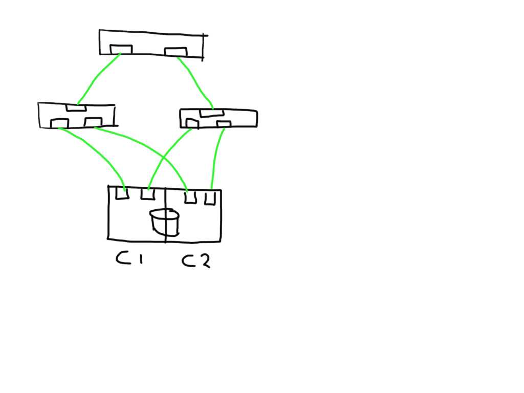 This shows a very simplistic SAN infrastructure where one host has 4 paths over two initiators to 2 storage ports each. All ports seem to be in tip-top shape.
 If one link (in this case between the switch and the storage controller) is observing errors (in any direction) the new ELS frame would increment that particular LESB counter value and the result would enable the host to detect the increase in any of the counters on that particular path. Depending on the policies of the operating system or application it could direct the MPIO software to mark that path failed and to remove it from the IO path list.
Similarly if a link shows errors between an initiator and switch it will mark 2 paths as bad and has the option to mark these both as failed.
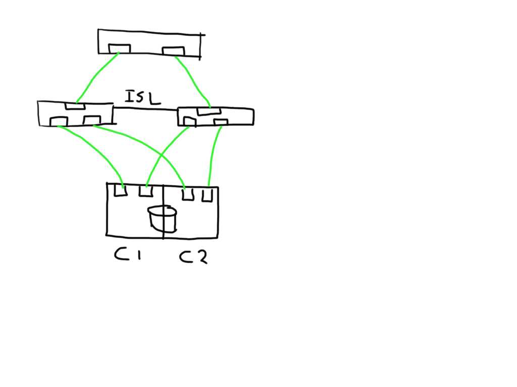
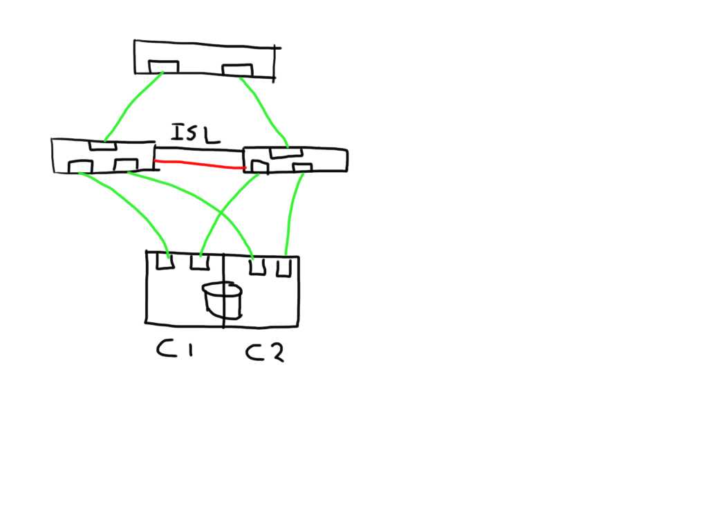
 If you have a meshed fabric the number of paths exponentially grow with each switch and ISL you add. The below show the same structure but because an ISL has been added between the switches the number of potential paths between the host and LUN now grows to 8
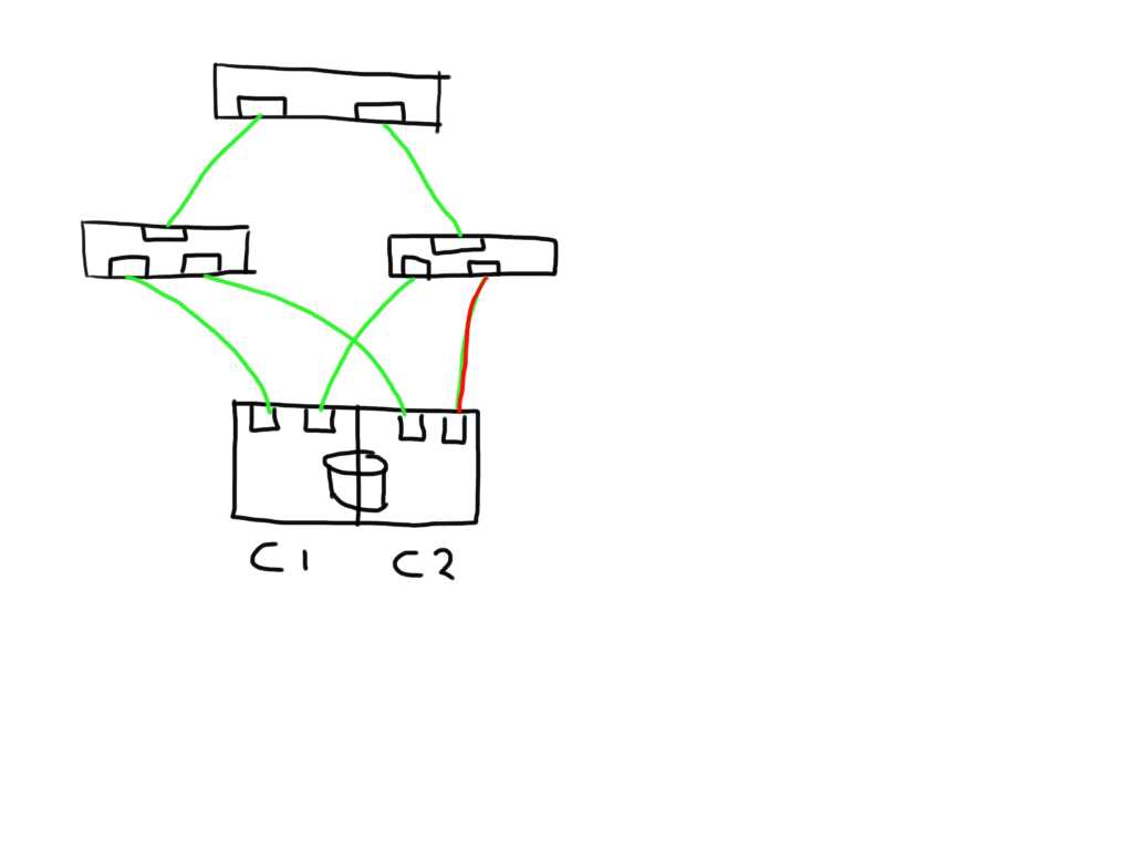
 This means that if one of the links is bad the number of potential bad paths also duplicates.
 In this case the paths from both initiators on this bad link are marked faulty and can be removed from the target list by the MPIOsoftware.
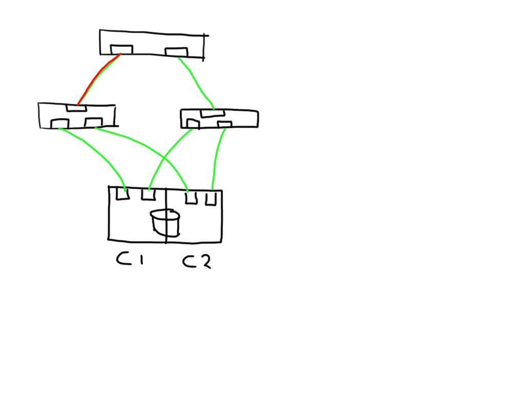
 The fun really starts with the unexpected. Lets say you add an additional ISL and for some reason this one is bad. The additional ISL does not add new paths to the path-list on the host since this is transparent and is hidden by the fabric. Frames will just traverse one or the other irrespective of which patch is chosen by the host software. Obviously, since the ELS is just a normal frame, the error counters in the ELS might be skewed based on which of the two ISL’s it has been sent. Depending on the architecture of the switch you’ll have two options, either the ASIC accumulates all counters for both ports into one and add these onto the already existing counters, or you can use a divisional factor where the ASIC sums up all counters of the ISL’s and divides them by the number of ISL’s. The same can be done for trunks(brocade) / portchannels(Cisco). Given the fact that currently most the counters are used in 32bit transmission words the first option is likely to cause the counters to wrap very quickly. The second advantage of a divisional factor is that there will be a consistent averaging across all paths in case you have a larger meshed fabric and thus it will provide a more accurate feedback to the host.
I’m working out the details w.r.t. the internals of the ELS frame itself and which bits to use in which position.
This all should make Fibre-Channel in combination with intelligent host-based software an even more robust protocol for storage based data-transmissions.
Let me know what you think. Any comments, suggestions and remarks are highly appreciated.
Cheers
Erwin
Errors and other nastiness on a serial transmission link
In some of my previous post I have outlined the reasons and consequences of errors on a link. There are multiple locations where a bit may flip from a 0 to a 1 or reverse. CRC errors, encoding errors, synchronisation and link failures are the usual symptoms and may lead to corrupted frames, primitives signals and primitive sequences. In the end they will lead to some sort of IO error or performance problem.
So where do these errors come from? The easiest ones to solve are those ones of a physical nature. Broken cables, wrongly fitted connectors, unclean connection points due to dust or incorrect handling of the cables. The ones who do not fall into these categories are much more difficult to detect. If you have checked and fixed your physical part of the puzzle we may need to dive in somewhat deeper into the “not-so-obvious” side of the fence and this is where it gets most interesting as well as complicated.
As you most likely know all current transmission protocols use a serial transmission link. This goes from 100Gb Ethernet to your SATA disk channel in your PC. Obviously Fibre Channel uses a serial transmission as well. As with many protocols the FC protocol is build upon layers and the serial transmission characteristics reside on the FC0 and FC1 layer.
 |
| A somewhat older picture of the FC stack |
The above picture more or less outlines the stack. Of course the speeds and feeds have increased but the general operations have remained the same.
So if the physical side is out of the way what could then cause a bit to flip. Well, pretty often a degraded SFP or incorrect settings on an ASIC may cause interference. When you look at the defect list from Brocade/Cisco and other vendors you’ll see so now and they defects popping up where they have adjusted so called “SERDES settings”. SERDES stands for SERializer/DESerializer which inherently implies they must be doing something on the chip which serialises and de-serialises the data stream. To go further into this we need to have a look how a basic flow of bits is being sent from the ASIC through the SFP onto the wire.
First you start of with 8 bits and this runs thru the encoder chip. Here the byte is split into two blocks of 5 and 3 bits after which an XOR mathematical calculation takes place and this results into 4 and 6 bit sub-blocks which are then glued back together so you end up in 10 bits. These still reside in a parallel way in a chip and thus it will be sent to the serializer. Based upon hardware implementation a FIFO buffer might in between these two. After it has passed the serializer it will be passed onto the SFP driver which converts it from an electrical to optical signal and puts in on the wire.
On the receiving side things are a bit more complicated. First of all it needs to align the incoming bitstream to a meaningful piece of information and therefore it has to align the clock speed to that bit-stream. Given the fact a 10-bit transmission character can hold more information then a 8 bit byte (duhh) means we end up with some additional characters which we can utilize. The most important one is the K28.5 character (also called a comma) which is send on the very first character of each frame as well as all primitive signals or ordered sets. (IDLE/R_RDY/NOS/OLS/LR etc..) Remember that FibreChannel is WORD aligned and each word consists of 4 transmission characters ie 40-bits. A primitive signal is thus 40 bits of which the first character start with K28.5 and then 3 “data” characters Dxx.x.
Depending on the current running disparity the K28.5 looks like 0011111010 on a negative RD or like 1100000101 on a positive RD. These two characters do never show up anywhere else in a bit-stream irrespective of payload. So when the very distinctive K28.5 arrives at the ingress port the receiver knows the exact point of which to align the synchronisation of the stream. The reason why this is needed is because there will always be a slight discrepancy on the frequency of the clocks between the remote and local side. The alignment of the clock via the bit-stream is a very effective way of achieving very high data-rates with accurate bit and word synchronisation. This would never have been possible with parallel link such as in the “old” SCSI days.
The de-serialized bitstream is thus sent a chip which effectively does the comma realignment after which it can be pushed into the decoding chip so the 10-bit transmission character can now be converted back to an 8-bit byte by applying the same XOR algorithm, in an inverse manner, which was used to encode the byte in the first place. After that is done the byte will be put into a, so called, elastic buffer. This nifty piece of chip is required to balance the ingress rate of which the bitstream arrives and the rate of which the ASIC or FPGA is able to pull the data from this interface. If the ASIC is able to pull the data quicker out of the interface than the interface can deliver the bit stream you end up in a so called underrun. If, on the other hand, the interface is delivering the data quicker than the ASIC can pull it out you may end up in an overrun. This is where the flexibility of the FC protocol comes into play with regards to fill-words. Basically it means that according to the standard each transmitting interface shall send at least 6 fill-words (either IDLE or ARB(FF))between two frames. The remote side however only needs to detect 3 to detect an inter-frame gap so it has a 3 word playroom to either add fillwords into the elastic buffer to prevent underrun or remove fillword in the event of overrun.
On 10GFC and 16GFC the 64b/66b encoding/decoding algorithm is used so it will pass a descrambler and block-sync chip before it is able to be decoded. Depending on vendor implementation there are some variation at which point the actual decoding is done. Most of these cases the decoder will pull the 66 bits out of the elastic buffer and decodes these on the fly when the ASIC does a read request to that interface.
As you can see there are many points where things might go wrong and it is thanks due to the brilliance of these hardware engineers that a BER of 10^15 is fairly normal.
So going back to these SERDES defects Brocade and others have popped up. What do they mean. These settings are to adjust the pre-emphasis settings of the serdes chip in such a way that it will over-drive the first transition and gradually underdrives on each subsequent bit of the same polarity. Huhhhh, what does that mean???
The 8b/10b encoding/decoding schema makes sure you will never have more than 5 consecutive ones or 5 consecutive zeros in a bit stream. If you run into a long string of consecutive ones or zero you will run into a phenomenon called ISI (Inter Symbol Interference). This means the transmission path capacitance may be higher than the discharge capability of that circuit after a short transition. In plain English it means the circuit charges itself to a higher rate that it can discharge it at the next transition.
So lets visualise this.
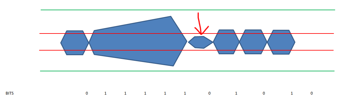
In the above picture the green line represents the upper and lower boundaries of the maximum voltage levels of the circuit and the red lines represent the upper and lower values were the end-point distinguishes between a 1 or a 0. (These are determined in the standards bodies of the respective interfaces. For Fibre Channel it is determined by the FC-PI-xx standard of the T11 committee). As you can see due to the over charge on the circuit after 5 ones the discharge on the transition is not big enough to fall outside the detection zone boundaries and thus the end-point is unable to detect a transition from 1 to 0 and thus it will result in an encoding error. There is a second problem with this and that is the fact of clock synchronization. There are two options for serdes chip to be able to synchronise the clock rate, SS or Source Synchronous and CDR (Clock Data Recovery). Source Synchronous requires a separate clock signal on the wire for the remote side to hook into whilst CDR is using a phase lock to the incoming bitstream and as such can adjust the clock-rate accordingly. (Remember the K28.5 ??) If however the transmission characteristics of this signal deter due to the ISI problem outlined above or any other issue the receiving side will lose synchronization and thus will need to first re-align itself again in order to be able to successfully be able to decode the bit stream. This will cause inflight frame to be lost and if the problem is persistent enough it will result in a severe performance problem or other nastiness.
With pre-emphasis the sending side will make sure there is a stepped degraded power-level on each subsequent bit and this will have the effect the capacitance value of the circuit will stay flat and the transition to the next different polarity will fall beyond the boundaries of the detection zone. An example of different pre-emphasis values show the effect on the eye-pattern below.
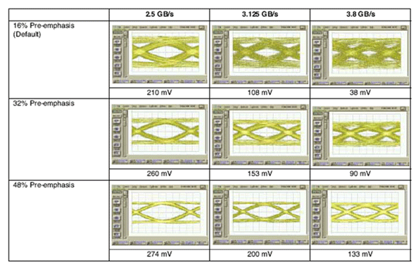
So when a vendor shows “defects” or “bugs” in relation to SERDES it does not mean there is really a hardware problem or software bug but more or less a way to track different settings on different ports to adjust the pre-emphasis values on those ports.
As you can imagine on a chassis with over 350 user ports and the even more ports on the back-end side of the fence there is a lot to track down and a change on one port may have a negative effect on other ports.
If we’re dealing with Brocade switches or directors the actual values are stored in the ASIC registers which can be collected via a supportsave. If you don’t know what you’re looking for then don’t even try. 🙂 There is also the option to adjust these values real-time however the previous comment is even more applicable. Unless you are a Brocade ASIC hardware engineer don’t even try. I did modify some values in a controlled lab environment and YES, thing do go haywire when entering values you pulled out of the hat.
Testing, testing… one-two-three…. For some advanced features.
Testing for a faulty port is always a bit tricky since you first need to know what you’re looking for and secondly you need to know what and how to interpret the outcome. Brocade has a utility in FOS called “portloopbacktest”. This utility allows you to test on a range of different options. the backdraw is that the switch needs to be in a non-operational (ie disabled) state.
If you’ve read the above you’ll see there are three distinct locations you need to test.
1. External to the SFP (ie the entire link including cabling, connectors, patch panels etc.)
2. External to the SERDES chip but before the SFP (ie internal ASIC/FPGA to SFP circuit)
3. Internal (parallel) to check for correct operation of encoding/decoding, elastic buffer, scrambler etc.
The below picture shows these three options. This is a snippet of a Virtex-II Pro RocketIO FPGA. You can see the layout of the TX and RX side with the SERDES chip, clock manager, encoder etc. Obviously depending on the vendor and usage you might see additional functionality being put into this like FEC calculators etc.
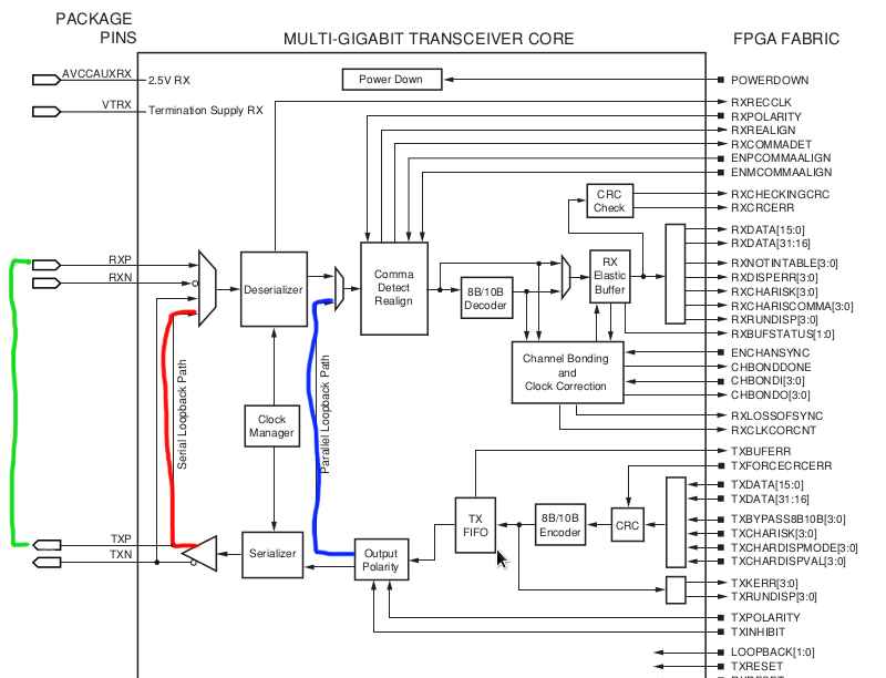
For option one you can use a loopback-plug directly on the SFP if you suspect a faulty laser or at the end of the link.
Normally you would start with the parallel test (Blue) and work your way up from there to the serial loopback (Red) and then the external one (Green). Also be aware the portloopbacktest uses a different port numbering schema than you might be accustomed to. This schema is based on the actual bladeport number according to the ASIC layout of the specific blade so it does not work based on the front-end port-numbers. This means that each blade type (16,32 or 48 port) will have a different numbering schema. Check the troubleshooting and command reference manual around these options.
On the 16G condor 3 hardware you can also use the new, so called, “D-Port” functionality. This however only works if you have two of these type of switches or 16G Brocade HBA’s connected to these 16G switches. If you implement these switches and/or HBA’s I would strongly suggest you test the link with this functionality as it can prevent future problems.
I hope this explains something around link errors you may find on fibre-channel ports and the cause plus resolution of it.
Let me know if you have further interest into different topics and I’ll see what I can cook up. 🙂
Cheers,
Erwin
ipSpace.net: FCoE between data centers? Forget it!
Cisco guru and long time networking expert Ivan Pepelnjak hits the nail on its head with the below post. It is one more addition to my series of why you should stay away from FCoE. FCoE is only good for ONE thing: to stay confined in the space of the Cisco UCS platform where Cisco seems to obtain some benefits.
Today I got a question around the option for long-distance replication between enterprise arrays over a FCoE link. If there is ONE thing that I would put towards the HDS arrays is that they are virtually bulletproof with regards to data-replication and 6x6x6 across 3 data-centres replication scenarios in cascaded and multi-target topologies are not uncommon. (yes, read that again and absorb the massive scalability of such environments.)
If however you then start to cripple such environments with a greek trolley from 1000BC (ie FCoE) for getting traffic back and forth you’re very much out of luck.
Read the below from Ivan and you’ll see why.
ipSpace.net: FCoE between data centers? Forget it!: Was anyone trying to sell you the “wonderful” idea of running FCoE between Data Centers instead of FC-over-DWDM or FCIP? Sounds great … un…
He also refers to a Cisco whitepaper (a must read if you REALLLYY need to deploy FCoE in your company) which outlines the the technical restrictions from an protocol architectural point of view.
The most important parts are that the limitation is there and Cisco has no plans to solve this. Remember though I referred to Cisco in this article all the other vendors like Brocade and Juniper have the same problem. Its an Ethernet PFC restriction inherent to the PAUSE methodology.
So when taking all this into consideration you have a couple of options.
- Accept business continuity to be less than zero unless the hurricane strikes with a 50 meter diameter. (small chance. :-))
- Use FibreChannel with dark-fibre or DWDM/CWDM infrastructure
- Use FCIP to overcome distances over 100KM
So far another rant of the FCoE saga which is stacking up one argument after another of why NOT to adopt it and which is getting more and more support across the industry by very respected and experienced networking people.
Cheers,
Erwin
Surprise: Cisco is back on the FC market
The Cisco MDS 9506,9509 and 9513 series director class FC switches have been in for the long haul. They were brought to market back in the early 2000’s (2003 to be exact) and have run a separate code-base from the rest of the Cisco switching family in the form of the Catalyst Ethernet switches. The storage and Ethernet side have always been a separate stream and for good reason. When Cisco opened up the can of worms with FCoE a few years back, they needed a platform which could serve both the Ethernet and fibre-channel side.
Thus the Nexus was born and a new generation of switches that could do it all. All ???? …. no, not really. For storage support you still needed native FC connectivity and hook this up to the Nexus which could then switch it via FCoE to either CNA’s or other, remote, FC switches to targets.
It seems the bet on FCoE didn’t go that well as the uptake on the entire FCoE protocol and convergence bandwagon has not taken off. (I wonder who predicted that :-)) This left Cisco a bit in a very nasty situation in the storage market since the MDS 9500 platforms where a bit at there end from an architectural standpoint. The updated supervisors to revision 2a plus the cross-bars were only able to handle up to 8G FC speeds plus the huge limitation of massive over-subscription on the high port-count modules (Marketing called it “host-optimised ports”) did not stack up against the requirements that came into play when the huge server virtualisation train took off with lightning speed. Their biggest competitor Brocade was already shipping 16G switches and directors like hot cakes and Cisco did not really have an answer. The NX5000 was limited regarding portcount and scalability whilst the NX7000 cost and arm and a limb so only for companies with a fair chunk of money who had the need to refresh both their storage switching as well as their network switching gear at the same time in addition to the fact they had enough confidence in the converged stack of FCoE this platform was a viable choice. Obviously I don’t have the exact number of NX7K’s sold but my take is that the ones that are sold are primarily used in high density server farms like the UCS (great platform) with separate storage networks hanging off of that via the MDS storage switches and maybe even these are direct connected to the server farms.
So it seems Cisco sat a bit in limbo in the datacentre storage space. It’s a fairly profitable market so throwing in the towel would have been a huge nut to crack so Cisco, being the company with one of the biggest treasure chests in Silicon Valley, pulled up their sleeves and cranked out the new box announce a few weeks ago, the all new MDS9710 based on new ASIC technology which now also delivers 16G FC speeds.
I must say after going through the data-sheets I’m not overly impressed. Yes, it’s a great box with all the features you need (with a couple of exceptions, see below) but it seems it was rushed to market from an engineering perspective to catch up with what was already available from Brocade. It looks like one or more execs switched into sub-state panic mode and ordered the immediate development of the MDS95xx successor.
Lets have a short look.
I’ll compare the MDS9710 and the Brocade DCX8510-8 since these are most aligned from a business market and technical perspective.
Both support all the usual FC protocol specs so not differentiation there. This includes the FC-SP, and FC-SB for security and Ficon (support for Ficon was not yet available at launch but I think that’s just due to qualification. It should be there somewhat later in the year.) What does strike me is that no FCoE support is available at launch of the product. Again, they could save that money and spend it more wisely.
There is not that much difference from a performance perspective. According to the spec sheets the MDS provide around 8.2Tbps FC bandwidth from a front-end perspective as does the DCX. Given the architectural difference between the MDS and the DCX you cannot really compare the overall switching capabilities given the fact the MDS switches frames on the cross-bar (or fabric-card as they seems to call it now) and the DCX on the ASIC level. From a performance standpoint you might gain a benefit by doing it the brocade way if you have the ability to have all ASIC locality however this also imposes limitations w.r.t. functionality. An example is link aggregation ie port-channel according to Cisco and trunking according to Brocade. (Do not confuse the Cisco “trunking” with the Brocade one.) Brocade requires you to have all members of a trunk to sit in the same port-group on a single ASIC whereas with Cisco’s method you don’t really care. The members can be all over the chassis so in case an entire slot fails the port-channel itself still keeps going. It seems Cisco learned its lesson from the over-subscription ratios that is hampering the high point-count modules on the 95xx series. The overall back-end switching capability of the 9710 seems to be more than sufficient to cater for a triple jump generation of FC and it seems likely the MDS could cated for 40G Ethernet in the not so distant future without blinking an eye. The 100G Ethernet implementation will take a while so I think this 97xx generation will sing out the current and next generation of 32G FC and 40G Ethernet. Since I don’t have insights in roadmaps I’ll direct you to the representatives of Cisco.
There is another thing that is bothering me and that is power consumption. The MDS (fully populated) draws a whopping 4615 watts of juice. Comparing that to the DCX8510-8, which needs less than half of that amount, it looks like somebody requested the ability to fry eggs on the box.
As for the software side Cisco bumped the major NX-OS level to 6.2 ( I don’t know what happened to 6.00 and 6.1 so don’t ask). Two of the major fabulous features that I like of NX-OS are VOQ and build in FC analysis with the fcanalyser tool. The VOQ (Virtual Output Queue) provides some sort of separate “Ingress” buffer per port so that in the case of a lack of credits on the destination of the frame this port does not cause back-pressure causing all sorts of nasty-ness.
From a troubleshooting perspective the fcanalyser tool is invaluable and just for that feature alone I would buy the MDS. It allows you to capture FC frames and store them in PCAP format for analysis via a 3rd party tool (like wireshark) or output to stdio raw text format so you can execute a screen capture on a terminal program. The later requires you know exactly how to interpret a FC frame which can be a bit daunting for many people.
As I mentioned in the beginning I’m not quite sure yet what to think of the new MDS as the featureset seems fairly limited w.r.t. portcount and innovation in NX-OS. It looks like they wanted to catch up to Brocade in which they very well succeeded but they have come very late to market with the 16G FC adoption. I do think this box has been developed with some serious future proofing build in so new modules and features can be easily adopted in a non-disruptive way so the transition to 32G FC is likely to be much quicker than they have done with the jump from 8G to 16G.
I also would advise Cisco to have a serious look into their hardware design regarding power-consumption. It is over the top to require that amount of watts to keep this amount of FC ports going whilst your biggest competitor can do with less than half.
To conclude I think Brocade has a serious competitor again but Cisco would really need to crank up the options with regards to port and feature modules as well as Ficon support.
Cheers,
Erwin
A less known "host-can’t-see-storage" problem caused by FC-SP authentication failures.
Many support-cases open with the line “Host can’t see storage” which puts most of these cases in the “configuration” queue. My assumption is that if a host can’t “see” storage it has never worked before so there must be some kind of config problem.
So once in a while you’ll see a case popping up where a less used feature of the FC protocol is used and that is FC Authentication (part of the FC-SP protocol.) This piece of the FC stack allows for an authentication mechanism between two ports on a link or an end-to-end connection.
The FC-SP protocol allows for a security check to be set up to prevent unauthorized access to fabric services. Basically it means if you don’t know my authentication method and access passwords I do not trust you and I will not allow you access to the fabric.
The fabric security architecture is build upon 5 components namely:
- Authentication Infrastructure
- Authentication
- Security Associations
- Cryptographic Integrity and Confidentiality
- and last but not least Authorization
I will not dive into each and every one of them since thats beyond the scope of this post. The Authentication part is fairly wide adopted by all HBA and switch vendors whilst the authorization and crypto services are only seen in very security environments.
Many initiators (mainly HBA’s) and targets (mainly storage devices) support the link authentication option but I haven’t come across an HBA vendor which also support the end-to-end authentication option.
The difference is depicted below.
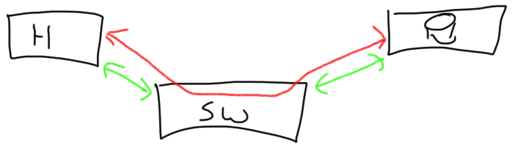
The individual (green) N_port-to-N-port are obviously the ports participating in the individual link authentication whilst the end-to-end (red) ports have an end-to-end authentication configured (These are not mutually exclusive and can be configured individually (if supported of course))
“So what does this have to do with my host not seeing storage?” you might ask.
Well, very simple. If you have configured anything in this entire setup incorrectly each port may refuse access and therefore you will not see any targets or luns.
It’s fairly easy to make a mistake in this configuration so lets have a look on the wire to see what the switch and HBA do when this option is turned on.
As an example I use an Emulex HBA but the HBA’s from Qlogic, Brocade etc have a similar setup.
When an HBA tries to obtain access to a fabric it first sends out a FLOGI (Fabric login). In this FLOGI it tells the fabric it’s id (WWN),which capabilities it has and what services plus classes it wants to use.
On of the parameters of these services is the “Security services” which is identified by a single bit in the “Common Services” parameter in this FLOGI.
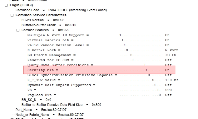
The switch in turn checks for this bit and either returns with an ELS accept or, in case the authentication is not configured on the switch, an LS reject.
In the picture below you see the accept. This doesn’t yet mean the ports have authenticated each other but merely have let each other know that they do want to start the authentication process.

Given the fact the FC-SP authentication infrastructure supports 3 methods of authentication (DH-CHAP, FCPAP and FCAP) we then need to establish the one we want to use. This is done with a ELS command coded 0x90

As you can see the HBA only can use 1 protocol and it wants to authenticate via DH-CHAP, it can use MD5 and SHA1 for hash marks and it can use 5 DH groups.
The accept from the switch is pretty straightforward:

As of this point the stage is set for the actual authentication. The ports have shown the do support the FC-SP protocol, they have set the DC-DHAP parameters which they are going to use so now they only thing that’s left is the actual exchange of shared secrets.
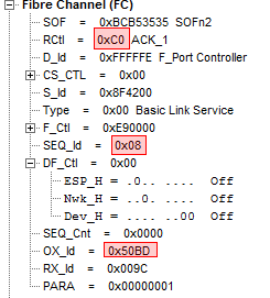
One of the interesting things is that as of this point the class of service changes to Class 2. As you can see in the trace the “Start-of-Frame” now initiates a class 2 exchange.

Given the fact class 2 means that we now require acknowledgement of frames we also see ACK_1 being returned for each frame being sent. Here the ACK_1 (C0) is sent from the switch to the HBA for sequence id 0x-08 of exchange id 0x50BD:
The DH-Challenge frame is then sent with the options the switch wants to use:
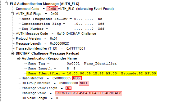
The command code is 0x90, with a 0x10 AUTH message code meaning I want to use DH-CHAP. The DHCHAP payload contains the parameters used in the challenge basically meaning I am WWN 10:00:00:00:05:1E:52:AF:00 , I use the MD5 hash in DH-group NULL and a value length of 16 bytes containing the following value.
This is still a Class-2 frame so an ACK_1 for acknowledgement is sent back prior to either an ELS Accept or reject.
If the HBA determines that these parameters are correct it will send an Accept back.

We are now at a point where the HBA trusts the switch but the switch has no clue he authenticated against the correct HBA so a DHCHAP reply from the HBA to the switch also has to be sent.

(What I did forget to highlight is that from a switch perspective it is the F-Port controller with Well-Known-Address 0xfffffe that takes care of the authentication and not the F-port itself. Just an FYI)
If the switch now determines these parameters are also correct an Accept is sent back and we have an authenticated session between these two ports.
The switch now sends a DHCHAP Success frame back which confirms the authentication status which is then acknowledge back by the HBA after which the rest of the usual FC handshaking takes place. (PLOGI,PRLI etc…)
The support problem.
Now the problem is that when we from support run into a “Host-cannot-see Storage” situation and the usual suspects like zoning, lun-masking have been excluded it will become very hard to check on situation like these since. Especially from a Brocade perspective it doesn’t provide much info besides the error messages which are not very useful beyond the fact it tells you that this error occurs and when it happens.
The second problem is that if this authentication is not used on the HBA nor the switch but the target requires this then there is no indication at all.
As an example the Hitachi arrays do support both link-level as well as end-to-end authentication.
The first one is set on the individual physical ports and the second one on the Host-Storage domains in the Authentication utility via Storage-Navigator. If you have an HBA with drivers which support this end-to-end authentication you can set this up but if these HBA drivers do not support this the security bit in the PLOGI (which is used to login to the array) is set to 0 the array will just ignore this frame and send a reject back.
From a troubleshooting perspective it is fairly hard to diagnose that because the switch logs do not show initiator to target frames. We would need to set up separate frame monitors and/or enable debug flags This is a rather cumbersome way of doing thing so my suggestion is to check if both link-level and end-to-end authentication is supported and if these are properly configured.
As a tip on Emulex you can check in OC Manager if your HBA and driver supports this. If you can switch between “Destination: Fabric (Switch)” and “Destination: Target” the driver does supports end-to-end. If not then only link level authentication is supported.
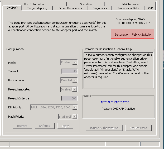
The option to enable FC-Authentication (and hence turn on the bit 21 in the common services parameter in the FLOGI) is in the “Driver Parameters” tab:

The HBA needs to be reset after configuring DH-CHAP to trigger a new FLOGI.
To all HBA/CNA/Switch/Array/Tape/(and anything else you can connect to a FC port) firmware engineers I would like to ask to provide simple on/off flags/commands on ports to either enable/disable full frame capture. The first word of a payload is obviously not sufficient to troubleshoot these kind of issues.
Hope this is of any help.
Cheers,
Erwin van Londen
The Emergency Health Threat (EHT) on Brocade FC fabrics
Since a couple of FOS versions ago Brocade wanted to fix the problem Fibre-Channel has by definition called credit back-pressure. The word “problem” overstated since in 99.99999% of all fabrics you’ll never see this anyway. As you know Fibre-Channel is a deterministic architected type of network which requires devices to behave properly. The chaos theory of Ethernet networks where flooding and broadcasts are more along the line of shoot the fly with a cannon doesn’t apply to Fibre-Channel.
So what is the issue then? By design two link-end points tell each other how many buffers they have available to store a FC frame during link initialization in the FLOGI (Fabric Login) phase. These is bi-directional so one side of the link can have 40 credits whilst the other only has three. This way the sending side know that it can send X amount of frames before it has to stop.
Below you see a snippet of a FC FLOGI trace plus the subsequent Accept.
The HBA tells the switch it has 3 buffers available so the switch is allowed to send a maximum of 3 frames before it need to wait for an R_RDY

The switch then returns with an accept in which it tells the HBA that it has 8 buffers available.

When the sending side transmits a frame it subtracts one credit from this amount. The receiving side on the other side of the link forwards the frame to its destination and sends a, so called, R_RDY (Receiver Ready) primitive back to the transmitting side which causes the number of outstanding credits to be increased by one again. So far pretty simple but imagine the following scenario.

I have three servers on the left and a storage array on the right with a switch in the middle. You see that the link between the storage array and the switch carries all traffic from all three servers. In a normal situation this is no problem as long as all devices behave as they should. Send a frame as long as a credit is available and wait for an R_RDY to return to replenish that credit. Now what happens if the blue server start behaving badly? ie. for some reason either it is starting to become very slow on returning these R_RDY primitives or the R_RDY is corrupted due to a physical link problem. The second scenario is pretty easy to figure out since the switch logs these kind of problems in the porterrshow plus this particular link will log a lot of LR entries in the fabriclog. (Have a look)
To get back to the problem you’ll see that at some point in time when the number of credits are all used from port #6 to port #3 the frames that are coming in on the switch ingress port #7 can no longer be forwarded to that port 6 and subsequent port #3. So these buffers on port 7 will fill up pretty rapidly which also means there is no room anymore for frames arriving from the array destined to be forwarded via port #5 to the green server or port #4 to the red server. So even when these two server have no problem at all they might get really impacted by the blue server. One way to overcome this is to shut down port #6 and you will see that traffic from the red and green server start flowing again. When there is a driver or firmware issue you will have some more troubles finding out what’s causing all this.
Now you may argue and say “listen dude, these frame do not sit in there indefinitely and at some point they will be discarded which allows for these buffer to be reused again so traffic starts flowing again.” Yes, you are right. There always has been a bit of a ballpark figure of a, so called, “hold time” which more or less meant that a frame may sit in an ingress buffer for X amount of time before the ASIC may discard that frame and free up the buffer and consequently return a R_RDY to the transmitting side. The issue is however that the transmitting port on the other side of the link might as well send a frame with the same troubled destination which also means that that frame will sit in the ingress buffer for that X amount of time. Brocade has used a formula to determine this “hold time” and on a default configured fabric this turns out to be 500ms. So in the previous example it may well be that for sending only two frames you lose an entire second. That’s an eternity in Fibre-Channel and storage so every precaution needs to be taken to prevent this from happening. Your performance across the fabric with sink through the toilet.
Now lets take this previous example one step further.
A fairly regular small to medium size SAN in a core-edge design looks a bit like this.

You have your servers on the left, the colored boxes are edge switches and the central ones are the cores. Nothing really fancy fancy but you already can see that from a trafficflow perspective it becomes pretty weird already since everything can go everywhere based on the source and destination routing paths that are set up during fabric build and FSPF routing calculations. Especially on the ISL’s between the two cores you see all traffic from all servers, disk arrays and tape drives. You can imagine that is things start to stack up somewhere you will end up in the same scenario are I described before but with this difference that all traffic on those core ISL’s can be affected. So even one device which sits behind the red switch and has a target on the purple switch may cause a problem to servers sitting behind the yellow switch going to a target behind the light blue switch. Similar the other way around since high latency devices or software issues might also be in the target devices.
So how do you overcome such a situation? Well, since we can’t predict failures to the exact minute we can try to circumvent one device clogging up traffic through the entire fabric. The best and only answer is something I described in my earlier blog posts (check the Rotten Apple series) to shut down the misbehaving port(s). My take is that if a port doesn’t work properly anyway plus it has a significant adverse effect on the rest of the entire fabric it is really a nobrainer to shut it down. Brocade FOS has pretty nifty tools like fabricwatch to get this sorted. It seems that from any logical, technical and reasonable standpoint this is the best option. Until politics get involved and from that point on all hell breaks loose. Every non-related, non-technical and non-reasonable argument is thrown back at you to prevent the automation of these great tools to shut down a misbehaving device. It’s like you know you’re being robbed and the police is ready to intervene and catch these criminals but some politician (or business owner in your case) doesn’t allow that so the robbers get away with the loot.
So the second best answer is that we need to drop frames on the edge switches sooner than on the cores. With the introduction of FOS 6.3.1b Brocade added a parameter which allowed you to adjust this edge hold time from around 100ms to the default 500ms. So this would in essence be a fairly average candidate to prevent these kind of credit back-pressure problems. The reasoning is that if the edge switch does not have any credits to forward a frame to the core-switch in a shorter period than the core-switch needs to forward it on its egress ports, there will be no overload on the core switch and thus no timing issues on that side. This allows the cores to keep moving traffic since those ingress ports will not be subjected to credit starvation since the frames are already dropped in an earlier stage and the outstanding buffer will be replenished sooner. In the end the result is that non-related traffic therefore will not be affected. There is however one major “gotcha”. This is a global switch setting on condor 2 platforms (which needs to be set on the default switch) and is applied PER ASIC AS SOON AS AN F-Port IS FOUND ON THAT ASIC. This means that if you share F-Ports and E-ports on a single ASIC the EHT is also applied on those E-ports so all returning traffic sitting in that Edge switch ingress port is immediately affected. So it is NOT a good idea to mix E-ports and F-ports on the same ASIC. What also is not a good idea is to have this EHT set too low (or tinkered with at all) on ASICs where target ports are connected since the argument is that one single target port might have a significant amount of fan-in ratio of devices and thus is more susceptible to somewhat elongated response times anyway which might affect timeing issues .
Although the EHT in general seems a great idea it can have some ramifications because what will happen on a very busy fabric where the credit_zero counters are already ramping up with significant speed. Reducing the time on which a frame can be sitting in a buffer might already be a problem. If frames are dropped due to timeouts whilst being allowed to sit around for 500ms will certainly be dropped with a much higher rate if the hold time is reduced.
Now here is where Brocade is currently shooting itself in the foot.
In subsequent versions, especially in the 7.0.1 and 7.1.0 releases they adjusted the default values from 500 to 220MS. ………. (keep thinking………)
Also there is a difference between Condor3 platforms (16G) and Condor2 platforms (8G) on the virtual circuits that live on the ISL’s plus the fact this is now configurable per logical switch (Condor3 platforms that is). Great fun if you have a mixed 8G and 16G blades in your DCX8510
Done thinking????
In general what we see in support is that many edge switches are embedded switches in blade-chassis and these fairly often fall under the responsibility of the server administrators. Now, I don’t want to discredit these fine folks, but in general they do not often take a look at the FC switches in this chassis. The result is that these switches are very often running old code. Now what happens if the storage admin decides to upgrade the core-switches to FOS 7.1.0x.??? The EHT will drop right away to 220ms since that’s the new default on that FOS version. The edge switches still run old code which have a default of 500ms hold-time so in a blink of an eye you now have a reversed EHT fabric where the edge switches (including the ones which might have bad behaving devices attached) are doing their job of trying to send a frame during 500ms but these frames will most likely be delayed much longer on the core-switches due to fan-in ratio and credit back-pressure and thus will be discarded at a much higher rate here than on the edge. Given the fact the EHT does not discriminate between frame on source and destination, all these dropped frames are likely to be from many, many initiators and targets across the fabric. This will results in the upper-layer protocols (like SCSI) having to re-drive their IO’s in addition to the normal workload and thus the parabolic eclipse of misery rises exponentially.
So what is my advice.
- First, keep all codelevels as up-to-date as possible.
- Monitor for bad-behaving devices, use FabricWatch AND SHUT THESE DOWN with the portfencing feature!!!!!!!!!!!!!! Preventing problems is always better that having to react on it.
- Make sure that if you use the EHT you configure it correctly. There are currently too many flaws in this feature that I wouldn’t recommend changing it to another value than the one we have used for decades and that is 500ms. If you fabric is up for it than keep it consistent across all switches in the fabric.
- Use bottleneck monitoring and alerting to identify high latency devices. Check these devices for up-to-date firmware and drivers and check if any physical issue might be the cause of the problem. (especially check the enc_out column of the porterrshow output.)
- Also use bottleneck monitoring to recover lost credits. Use the “bottleneckmon –cfgcredittools -intport -recover onLrOnly” command to have FOS fix credit issues on back-end links.
From a design perspective we often see schema’s which resemble the picture I’ve drawn above. A core-edge design with servers on one side and target on the other. Personally i think this is the worst design you could think of since it is susceptible to all sorts of nasty thing of which physical issues are the most obvious and easy to fix. Latency and congestion are a very different ballgame so keeping initiators and target as close as possible to each other has always had my preference. Try to localize per port-group, then ASIC, then blade, then switch and last per hop count. This will give you the best performing and most resilient fabric.
!!!!!!!!!!! UPDATE April 3rd 2013 !!!!!!!!!!!!
I’ve got some feedback from Brocade based on some questions we had:
In case of existing Fabric where EHT is 500ms and you insert a brand new 8510 in the core, the 8510 is set to 220. What is Brocade’s recommendation?
- Brocade’s recommendation is to change the EHT for the new 8510 in the core to 500ms
- Once set to 500ms on the 8510, any firmware upgrades to the DCX or 8510 will retain the EHT settings of 500ms
Can you set EHT on condor3 by port? Where can we check this setting in Supportsave logs?
- You can’t set EHT by port … it is still one setting for the switch, but that setting will only take effect on individual ports based on the ASIC and port type:
Condor-2
- ASIC has only F-ports. The lower EHT value will be programmed onto all F-ports
- ASIC has both E-ports and F-ports. All ports will be programmed with 500ms
- ASIC has only E-ports. All ports will be programmed with 500ms
Condor-3
- ASIC has only F-ports. The lower EHT value will be programmed onto all F-ports
- ASIC has both E-ports and F-ports. The lower EHT value will be programmed onto all F-ports, and 500ms will be programmed onto all E-ports
- ASIC has only E-ports. All ports will be programmed with 500ms
- You can see the current value set by using the following CLI command:
configshow | grep “edge”
switch.edgeHoldTime:500
- This should also be part of the system group, configShow command in the Supportsave
What is the real default for FOS 7.x 220 or 500?
- Brand new system, newly installed with 7.X firmware: Default will be 220
What is Brocade’s Best practice? 220 on edge and 500 in core?
- Yes, from our testing, we have shown this to be the optimal setting.
Additional info:
- Existing DCX upgraded from 6.4.2 or 6.4.3 to 7.X: Setting will remain at 500ms with one exception :
Upgrading from 6.4.2 or 6.4.3, the 6.x default of 500ms will be retained, with one exception: If the configure command had never been run before, and the very first time it is run is after upgraded to 7.X then the EHT will use the 7.x default of 220ms (I don’t think this should be a concern because every end user would have run the configure command. I think this would only apply on a new unit shipped with 6.x, never installed/configured, then upgraded to 7.x, then configured. In this case it would appear as a “new” 7.x install with 7.x default).
=================================================================
As mentioned above there will be some separate documentation around this topic. My preference would be to have the ability to segregate core from edge-switches plus manually be able to differentiate between E- and F-ports irrespective of FOS version and/or chip type but I also do acknowledge this might not be a real option on older equipment.
Hope this helps a bit if you get confused by the different options and settings regarding this Edge-Hold-Time.
Regards,
Erwin
PS. The “hold-time” formula I mentioned above is ((RA_TOV – ED_TOV)/(max_hops + 1))/2 which by default translates to (10000ms-2000ms)/(7+1)/2=500ms
and PPS: pardon my drawing skills. 🙂
Why convergence still doesn’t work and how you put your business at risk
I browsed through some of the great TechField Day videos and came across the discussion “What is an Ethernet Fabric?” which covered the topic of Brocade’s version of a flat layer 2 Ethernet network based on their proprietary “ether-fabric protocol”. At a certain point the discussion led to the usual “Storage vs. Network” and it still seems there is a lot of mistrust between the two camps. (As rightfully they should. :-))
For the video of the “EtherFabric” discussion you can have a look >>here<<
Convergence between storage en networking has been a wishful thinking ever since parallel SCSI became in it 3rd phase where the command set was separated from the physical infrastructure and became serialised over an “network” protocol called Fibre-Channel.
The biggest problem is not the technical side of the conversion. Numerous options have already been provided which allow multiple protocols being transmitted via other protocols. The SCSI protocol is able to be transmitted via FibreChannelC, TCPIP, iSCSI and even the less advanced protocol ATA can be transferred directly via Ethernet.
One thing that is always forgotten is the intention of which these different networks were created for. Ethernet was developed somewhere in the 70’s by Robert Metcalf at Xerox (yes, the same company who also invented the GUI as we know it today) to be able to have two computers “talk” to each other and exchange information. Along that path the DARPA developed TCP/IP protocol was bolted on top of that to make sure there was some reliability and a more broader spectrum of services including routing etc was made possible. Still the intention has always been to have two computer systems exchange information along a serialised signal.
The storage side of the story is that this has always been developed to be able to talk to peripheral devices and these days the dominant two are SCSI and Ficon (SBCCS over FibreChannel). So lets take SCSI now. Just the acronym already tells you its intent: Small Computer Systems Interface. It was designed for a parallel bus, 8-bits wide, had a 6 meter distance limitation and could shove data back and forth at 5MB/s. By the nature of the interfaces it was a half-duplex protocol and thus a fair chunk of time was spent on arbitration, select, attention and other phases. At some point in time (parallel) SCSI just ran into brick wall w.r.t. speed, flexibility, performance, distance etc. So the industry came up with the idea to serialise the dataflow of SCSI. In order to do this all protocol standards had to be unlinked from the physical requirements SCSI had always had. This was achieved with SCSI 3. In itself it was nothing new however as of that moment it was possible to bolt SCSI onto a serialised protocol. The only protocols available at that time were Ethernet, token ring, FDDI and some other niche ones. These ware all considered inferior and not fit for the purpose of transporting a channel protocol like SCSI. A reliable, high speed interface was needed and as such FibreChannel was born. Some folks at IBM were working on this new serial transport protocol which had all the characteristics anyone would want in a datacentre. High speed (1Gbit/s, remember Ethernet at that time was stuck at 10Mb/s and token ring at 16Mb/s), both optical and copper interfaces , long distance, reliable (ie no frame drop) and very flexible towards other protocols. This meant that FibreChannel was able to carry other protocols, both channel and network including IP, HIPPI, IPI, SCSI, ATM etc. The FC4 layer was made in such a flexible way that almost any other protocol could easily be mapped onto this layer and have the same functionality and characteristics that made FC the rock solid solution for storage.
So instead of using FC for IP transportation in the datacentre some very influential vendors went the other way around and started to bolt FC on top of Ethernet which resulted in the FCoE standard. So we now have a 3 decade old protocol (SCSI) bolted on top of a 2 decade old protocol (FC) bolted on top of a 4 decade old protocol (Ethernet).
This in al increases the complexity of datacentre design, operations, and troubleshooting time in case something goes wrong. Although you can argue that costs will be reduced due to the fact you only need single CNA’s, switchports etc instead of a combination of HBA’s and NIC’s, but think about the fact you lose that single link. This means you will lose both (storage and network) at the same time. This also means that manageability is reduced to zero and you will to be physically behind the system in order resuscitate it again. (Don’t start you have to have a separate management interface and network because that will totally negate the argument of any financial saving)
Although it might seem that from a topology perspective and the famous “Visio” drawings the design seems more simplified however when you start drawing the logical connections in addition to the configurable steps that are possible with a converged platform you will notice that there is a significant increase in connectivity.
I’m a support engineer with one of the major storage vendors and I see on a day to day basis the enormous amount of information that comes out of a FibreChannel fabric. Whether it’s related to configuration errors, design issues causing congestion and over-subscription, bugs, network errors on FCIP links and problems with the physical infrastructure. See this in a vertical way were applications, operating systems, volume managers, file-systems, drivers etc. all the way to the individual array spindle can be of influence of the behaviour of an entire storage network and you’ll see why you do not want to duplicate that by introducing Ethernet networks in the same path as the storage traffic.
I’m also extremely surprised that during the RFE/RFP phase for a new converged infrastructure almost no emphasis is placed on troubleshooting capabilities and knowledge. Companies hardly question themselves if they have enough expertise to manage and troubleshoot such kind of infrastructures. Storage networks are around for over over 15 years now and still I get a huge amount of questions which touch on the most basic knowledge of these networks. Some call themselves SAN engineers however they’ve dealt with this kind of equipment less than 6 months and the only thing that is “engineered” is the day-to-day operations of provisioning LUNs and zones. As soon a zone commit doesn’t work for whatever reason many of them are absolutely clueless and immediate support-cases are opened. Now extrapolate this and include Ethernet networks and converged infrastructures with numerous teams who manage their piece of the pie in a different manner and you will, sooner or later, come to the conclusion that convergence might seem great on paper however there is an enormous amount of effort that goes into a multitude of things spanning many technologies, groups, operational procedures and others I haven’t even touched on. (Security is one of them. Who determines which security policies will be applied on what part of the infrastructure. How will this work on shared and converged networks?)
Does this mean I’m against convergence? No, I think it’s the way to go as was virtualization of storage and OS’es. The problem is that convergence is still in its infancy and many companies who often have a CAPEX driven purchase policy are blind to the operational issues and risks. Many things need to be fleshed out before this becomes real “production ready” and the employees who keep your business-data on a knifes-edge are knowledgeable and confident they master this to the full extent.
My advice for now:
1. Keep networks and storage isolated. This improves spreading of risk, isolates problems and recoverability in case of disasters.
2. Familiarise yourself with these new technologies. Obtain knowledge through training and provide your employees with a lab where they can do stuff. Books and webinars have never been a good replacement for one-on-one instructor led training.
3. Grow towards an organisational model where operations are standardised and each team follows the same principles.
4. Do NOT expect you suppliers to adopt or know these operational procedures. The vendors have thousands of customers and a hospital requires far different methods of operations than an oil company. You are responsible for your infrastructure and nobody else. The support-organisation of you supplier deals with technical problems and they cannot fix your work methods.
5. Keep in touch with where the market is going. What looks to become mainstream might be obsolete next week. Don’t put your eggs in one basket.
Once more, I’m geek enough to adopt new technologies but some should be avoided. FCoE is one of them at this stage.
Hope this helps a bit in making you decisions.
Comments are welcome.
Regards,
Erwin van Londen