I’ve written about fillwords a lot (see here, here, and here) but I didn’t show you much about the different symptoms an incorrect fillword setting may incur.
As you’ve seen fillwords are a very nifty way of maintaining bit and word-sync on a serial transmission link when no actual frames are sent. Furthermore they also are replaceable with other primitive signals (Like R_RDY, VC_RDY etc) to utilize a very simple instruction method between two ports without interfering with actual frames. That means that fillwords are ALWAYS squeezed in between frames.
I’ve been focusing on the implications of physical issues a lot in my posts over the last ~2 years. What I haven’t touched on is logical performance boundaries which also cause extreme grief in many storage infrastructures which lead to performance problems, IO errors, data-corruption and other nasty stuff you do not want to see in your storage network.
For years many storage environments have used both active-active and active-passive multipath (MPIO) access mechanisms to access storage arrays in a dispersed or linear method. On enterprise class storage arrays with global caches the active-active method is most often used while on modular arrays you’ll see the active-passive scenario often applied. Inherently this means that during absence of IO, whether being the passive path or due to total non-IO operations (ie. there is no application or operating system sending or receiving any data), the actual fibre-channel links are only sending IDLE or ARB(ff) fillwords to maintain bit- and word synchronization. This also means that both the sender and receiver are always up and thus use the same amount of power as where they transmitting data at full line-rate. Obviously this is a waste of scarce resources and this is what has been addressed in the new FC standards that are coming up. The FC framing and signalling standard will be enhanced to have traffic diagnostics determine if an SFP should be in full power operating power or in a power reduced mode. Below are the details including some cost-savings calculations.
I’ve been writing about troubleshooting issues for a while now and one of the things that is very difficult and most time consuming is correlating events between host systems, switches and storage arrays in the even of storage related errors. My advice has always been the same. Hook everything up to NTP systems, make sure that time and date settings, including time-zones and DST settings do fall within the drift values of the NTP client and that little nifty piece of software will make sure time is equal on all systems. (See below how to accomplish this.)
There are however some issues when this is not fully followed through and virtual switches are used.
The FC frame header has not changed since its inception back in the late 80-ies. This shows the absolute rock-solid backward compatibility towards previous generation platforms and vendors. Obviously the the FC protocol itself has grown and evolved with marked demands to provide an extremely flexible transport mechanism for the most demanding storage environments. When you start to design a new protocol the concept of future proofing is a must and sits very high on the top of the design list. Not only does it require insight into current markets and requirements but also a huge set of extremely smart brains to come up with possible scenario’s of what might be required in years to come. You don’t want it to become obsolete in 5 years time because there were inherent flaws in the protocol. Next to that your have to facilitate options which allows for flexible expansion of functions and features of which none of the above brains had ever thought of. (Did somebody know about VMware back in 1990?) The concepts of NPIV where not on the radar back then. So what is the structure of this protocol that makes it so flexible.
Well, almost… 32GFC is fixed and at the standard has been ratified and the physical specs are moulded in concrete. In addition to this there are functions that enable to combine 4 of these into a single 128Gb link. Yes 128Gb/s. That’s fast….Ohhh wait… thats only ONE WAY which means a single link can push 256Gb/s in total. That allows you to push 25600MB per second through a link. In order to achieve these transmission speeds there has been a somewhat restructuring on the individual requirements w.r.t. quality of the actual link.
In Fibre-Channel, and many other network protocols, the use of CRC (Cyclic Redudancy Check) is adopted to detect corruption of frames. Be aware of the word “frames”!! As I explained in previous posts there are two layer of link integrity, an 8b/10b encoding/decoding algorithm (on 10G and 16G FC it has been changed to 64/66) which ensures dc balance plus error detection on the FC1 layer plus CRC which provides an additional check on the FC2 layer. Primitive signals or sequences are not frames and thus are not guarded with a CRC check.
Crc has the benefit that it can calculate on a serial bitstream as opposed to some other methods which require a certain fixed size of data in order to provide an integrity check. (A PKI like infrastructure is something along these lines such as GPG which can cryptographically sign an email message based on the entire content before it is sent). Secondly the calculation and reverse checking is very simple which means it can be build in hardware (ASICs or FPGA’s) without the need for software spending CPU cycles on both ends of the link which would have a serious impact on performance. There is absolutely no integrity check or security mechanism build into crc so any content can easily be modified, the crc recomputed and forwarded without the receiving side knowing it. In my test environments I use such methods to change an FC frame in-flight in order to see the behaviour of the modified content on the HBA or array. This allows me to inject data to test on protocol errors and the subsequent actions. (If I wasn’t able to recompute the crc, the destination port would detect the incorrect crc and just discard the frame.)
Now, going back to Fibre Channel. The CRC is calculated from the Start Of Frame (SOF) until the last word of the payload and is then appended to the frame. The FC2 layer will then add an End Of Frame (EOF) with a status qualifier. (I get back to this later).
FC frame
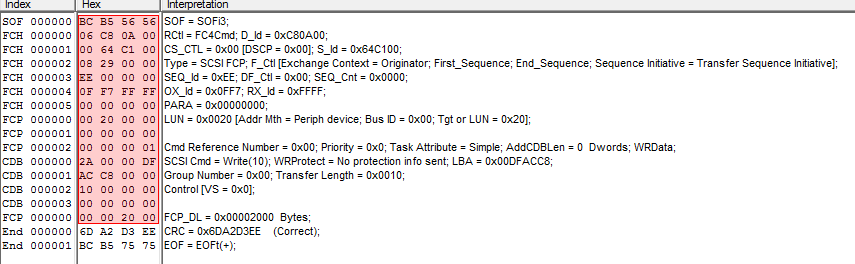
Below a screenshot of a FC trace where the host issued a write(10) command to lun 32. The CRC is determined to be correct and the frame is ended with a EOFt (terminate, this doesn’t mean the IO is terminated but this sequence of the FC exchange is completed. I won’t go into this any further)
If for any reason one or more bits in the bitstream between the SOF and last bit of the payload is changed the receiving side will do a reverse crc check which obviously will fail.
Now, I mentioned that the calculation is done inline of the bitstream. These days all fibre-channel implementations from all vendors use cut-through switching which more or less means that as soon as the first word of the FC frame is received (the one that contains the DID Destination ID or FCID) it is immediately forwarded to the out-port of that switch having the route set up according to FSPF. The second word of the frame may not even have arrived in full yet. This ensures optimal performance with next to no latency from a switching algorithm perspective. If you then do some maths and calculate the length of a FC frame it means that the first word of the frame may have already arrived at its final destination before the last word of the frame has even left the source.
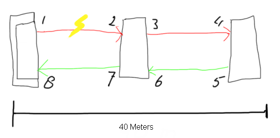
In the above picture you see a representation of three switches (pardon my drawing skills). Switch number one on the left has received a frame from an HBA and is sending this out on port 1. The frame is 1KB in size and the link speed is 8Gb/s. This means that the length of the frame is almost 250 meters long. If one or more bits flip at the 512th byte on the link between 1 and 2 the beginning of the frame is already at it’s destination so nowhere in the entire FC path any form of correction can be done. (there is an exception called FEC but I’ll discuss this in a later post). What will happen is that the port at (2) will detect the crc error and it will replace the EOFn or EOFt with a EOFni or EOFti (the i means invalid.) All switches will forward the frame to its destination (unless the DID in the frame-header is the part which is corrupt). As soon as the EOFxi arrives at the destination it can immediately discard the entire frame, clear the buffer and start the recovery procedures. If the intermediate switch detects the crc error and it would have discarded the frame over there both the initiator and target would have no clue what’s going on and would rely on the default FC and SCSI timeout values before is would be able to act on these.
From a troubleshooting perspective if you now look on the error counters on the switch ports (on a Brocade platform) you will see that port (2) will have logged the crc error in two columns of the porterrshow output: the crc_err and crc_g_eof (CRC error with a good EOF). Since the intermediate switch still forwards the frame port (4) will also detect the same crc error however since port (2) changes the EOFx into an EOFxi (invalid) port only the crc_err column on this port is incremented and not the crc_g_eof column. This mechanism allows you to follow upstream paths and determine where these errors originate from.
Hope this brings some insight and gives you better info of how to interpret these kind of errors.
The storage world has always been predictable (from a technical side that is. :-)) This means that data coming from an application through server and traversing a multitude of connected devices to a spindle (in whatever form or shape) takes the logically shortest, fasted and best available route. These routes are calculated based on a protocol called FSPF. (Fabric Shortest Path First) and is somewhat analogous to OSPF in the networking world.
Both OSPF and FSPF are based on Dijkstra’s algorithm of mathematically calculating the shortest path between any two given points. When you fire up Google maps and use the “Directions” option to get a route from A to B the same algorithm is used. Obviously you can adjust the paths between those two points to either include or exclude certain criteria like distance, speed etc. on which you let loose the Dijkstra calculations. To go back to storage the results of the calculations in addition to secondary criteria (zoning, route-costs etc.) determines the routes that are programmed into the ASICs or cross-bar switches. So what does this have to do with load-sharing and delivery ordering??
Pretty often you get into some sort of mode whereby I forget that there are many youngsters getting their feet wet in the storage arena and some things are hard to grasp on. Traffic flow is one of them so here we go. Continue reading →
Sigh….. yet another post to debunk some FCoE marketing and explain in some more details why FCoE is not good for Business Continuity (or business in general). Continue reading →


 In the above picture you see a representation of three switches (pardon my drawing skills). Switch number one on the left has received a frame from an HBA and is sending this out on port 1. The frame is 1KB in size and the link speed is 8Gb/s. This means that the length of the frame is almost 250 meters long. If one or more bits flip at the 512th byte on the link between 1 and 2 the beginning of the frame is already at it’s destination so nowhere in the entire FC path any form of correction can be done. (there is an exception called FEC but I’ll discuss this in a later post). What will happen is that the port at (2) will detect the crc error and it will replace the EOFn or EOFt with a EOFni or EOFti (the i means invalid.) All switches will forward the frame to its destination (unless the DID in the frame-header is the part which is corrupt). As soon as the EOFxi arrives at the destination it can immediately discard the entire frame, clear the buffer and start the recovery procedures. If the intermediate switch detects the crc error and it would have discarded the frame over there both the initiator and target would have no clue what’s going on and would rely on the default FC and SCSI timeout values before is would be able to act on these.